Part Design is the key to success and our top tip is “KEEP IT SIMPLE”.
In order for designs to be fully optimised for injection moulding, key points to be considered are:
1) Function and quantities
- Understand the function of the part and how it will be used. This will help determine potential weak zones or areas requiring additional strength.
- What are the interfaces, both between moulded parts and with associated hardware such as pcb’s? Moulding tolerances will need to be allowed for.
- Quantities will determine the type of tooling required and can have a bearing on tool material.
2) Material Choice
- Will depend on the function and aesthetics of the part (as above).
- Thermoplastics flow differently under heat and pressure, especially if fillers are involved, therefore certain combinations of geometry and feature size may not be possible.
- Consider using fillers, this could be for strength (eg glass fibres), impact resistance or aesthetics.
- Colour is usually added to the thermoplastic before moulding. This can be as a masterbatch, or compounded, depending on the quantities concerned. Different colours can highlight different issues within the moulding. An alternative is that the part can be painted at a later stage.
- Cost may be a deciding factor – the cheaper resins are those that are more common, for example, acetal (POM), acrylic (PMMA), Acrylonitrile butadiene styrene (ABS), High-density polyethylene (HDPE), Polycarbonate (PC), Polycarbonate/ABS (PC/ABS), Polypropylene (PP), Polystyrene (PS).
3) Wall thickness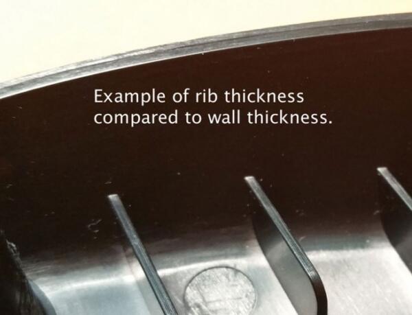
- Keep wall thickness’s constant where possible.
- If design limitations mean it is impossible to have uniform wall thicknesses, then transition between different thicknesses should be as gradual as possible.
- Ribs can be used to increase the bending stiffness of a part whilst keeping wall thickness at a minimum. Rib thickness must be less than the wall thickness to avoid sinkage issues.
- Maximum wall thicknesses are material dependent and can vary dramatically so it’s worth checking. Ideally we are looking around the 2mm-4mm range, however 0.6mm-6mm is possible.
- If thicker walls are a must, there are alternative ways to do this, e.g. foaming. If this is the case for your part, talk to us and we can help.
4) Draft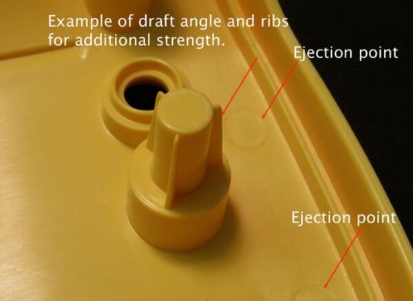
- To ensure the part comes out of the mould smoothly, all surfaces in the line of draw need to be drafted (or tapered). This allows the mould tool to open and the part surface to move away from the mould wall quickly and not be dragged across it.
- Lack of draft will result in the moulded surface showing cosmetic flaws (drag marks) and potentially cause the part to grip the core so tightly ejection is impossible. The addition of textures increases the need for draft to avoid scuffing the texture. Draft angles need to be considered within the design of the part from an early stage.
5) Sharp corners
- Sharp corners should be avoided to prevent part failure. Rounded corners are much easier for the material to flow around allowing the mould to fill evenly and minimise any internal stresses. The cooling process is also more regular, reducing the risk of fragile corners in the end product.
- The radius of corners must be considered as the stress concentration factor varies with radius for a given thickness. We recommend that the inside radius is a minimum of 1 x the thickness.
6) Solid Areas
- Core out large solid areas to leave a standard wall thickness where possible to avoid sink. Sink occurs when hot material that is too thick in the mould cools and contracts inwards, causing the centre to ‘sink.’
- Gussets and ribs can be added into a design to help reduce warping where solid areas have been removed.
7) Injection and ejection points
- The injection and ejection points must be considered to avoid marks and blemishes on cosmetic surfaces or critical features.
8) Undercuts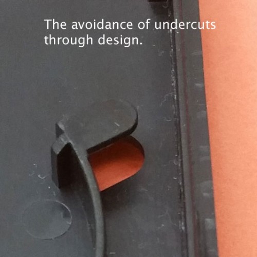
- Tools open linearly and as a result undercuts need to be released by side actions, which in turn add to tool cost. Minimising undercuts through clever design will not only simplify the tooling but will frequently improve cosmetics, as each side action will leave a witness on the part.
9) Finish
- Consider the texture of the part – a coarser finish may help hide minor imperfections such as knit lines but will require more draft.
- Is lettering required on the finished part?
- Correct placement of lettering can avoid introducing additional side actions.
10) Costs
- To manufacture a tool is a non recurring cost and is incurred before a single part is produced. It is unlikely that any type of injection tooling is going to cost less than £1000 and for complex tools there is no upper limit.
- As a general rule, the higher the number of parts being produced, the lower the piece part cost. However, with differing tool techniques, low volume injection moulding can be commercially viable for quantities as low as 50 parts depending on the geometry and size.
- Parts can be combined in a single tool, often referred to as a 1+1, (ie 2 geometries in a single tool) if materials and colours are the same, resulting in a cost saving.
Plunkett Associates are well known as specialists in low volume injection moulding. Optimising the design data is part of the service we provide alongside support and advice to get the best part possible for you. If this is an option you have been looking into, contact us, either by phone or email and we will be happy to discuss your project with you.