
LINKING SERIOUS BUYERS TO THE BEST SUPPLIERS
Serving the UK & Irish plastics industry
The elimination of static charge is required in a number of scenarios:
INJECTION MOULDING – The dropping of numerous small plastic parts into a container creates high levels of static charge, which attracts dust and can also give the operators unpleasant shocks.
CLEANROOM MOULDING - Static Electricity attracts small particle contaminants naturally found in the air.
VACFORMING – Both the sheets prior to processing and formed products can stick together when stacked, making handling difficult, as well as attracting dust.
POLYTHENE CONVERSION - Static Electricity causes problems throughout the bag making and conversion industry.
BLOW MOULDING – Whether pre-forms attracting dust or the final labelling of a finished product, static can lead to product contamination or cause other issues.
The method of static elimination depends mainly on the type of application. Both short and long-range static elimination devices are available, e.g. Anti-Static Ionising Bars that use an electric field to break down gas molecules into positively or negatively charged ions. If a plastic component is positively charged, it will attract negative ions until neutralised.
Sometimes Ionised air blowers are used; creating ions and then blowing them over long distances. This is a good solution if bulky three-dimensional products are involved, or there is a need to remove static from a hard to reach area, e.g. an internal surface.
Visit Here to contact the leading UK companies that can provide you with advice and quotes for your Anti-Static requirements.
Bulk conveying equipment refers to equipment that is used to transport plastic raw material in large quantities and over long distances. This could be to load and discharge material silos or to ‘pump’ material around a material distribution system that feeds multiple processing machines.
Vacuum Pumps use a similar principle to three phase hopper loaders but on a much larger scale. They typically draw material from bulk storage into smaller receivers within the manufacturing plant. These, in turn, are emptied by loaders on the individual machines. The material can travel long distances through specialised pipework that has no sharp bends.
Mechanical devices typically use a revolving helix (Archimedes screw) to transfer material. This solution can handle a much wider range of materials, for example, re-grind that varies in size and would clog a vacuum type system.
Visit Here to contact the leading UK companies that can provide you with advice and quotes for your Bulk Conveying requirements.
As the name suggests, a Cleanroom provides a controlled environment that is intended to be cleaner than a typical working environment. A ‘White Room’ is one stage below this, being, for example, an injection mould shop that has a higher than typical level of house-keeping and procedures designed to reduce the risk of product contamination.
By definition, a Cleanroom provides a physical barrier that isolates an area from outside influences and reduces the ingress of contaminants. The particular process and application involved dictate the degree to which contamination levels are controlled. Ways to reduce these levels include:
The level of contaminant control achieved by a particular design is designated by an ISO system. This standard provides a combination of maximum particle size allowed and concentration levels in terms of the number of particles/m3 of air.
ISO 9 is the lowest classification, having similar to normal outdoor air quality levels. The other extreme is ISO 1, this only allowing a maximum of 10 particles per cubic metre, with a maximum particle size of 0.1 microns.
In typical plastic moulding applications, classification of ISO 7 or 8 is typical. This is usually sufficient for the production of medical devices, although it may still be necessary to pre-treat some products before packaging them in a sterile container. Achieving a higher standard than this is possible, but moulding machines (even when electrically driven) and mould tooling cannot by nature be completely clean, eg. Because a degree of lubrication is needed. The usual need to remove tooling at some stage also means there is often an access area required in the roof of the structure.
Visit Here to contact the leading UK companies that can provide you with advice and quotes for your Cleanroom requirements.
Predominantly used for removing and isolating dust and other light-weight contaminants from reprocessed material. The majority of equipment uses a cyclonic principle (an air vortex) ‘down-stream’ from a granulator or shredder to separate dust and items such as paper fragments. The ‘cleaned’ or ‘air-washed’ material is then isolated from the removed contaminants.
A typical example would be the reprocessing of PET bottles that have been shredded/granulated with their paper labels in place. By effectively removing the small pieces of paper, the re-grind is more likely to be suitable for directly re-processing, without having to be turned back into pellet form.
Visit Here to contact the leading UK companies that can provide you with advice and quotes for your De-dusting requirements.
This equipment is typically used once plastic parts have been manufactured, one notable exception being digitally printing information onto an extruded profile as it passes along the final stages of the production line.
Printing most commonly involves the pad printing of a relatively flat surface. A machine fitted with a rubber pad transfers a coloured medium onto the surface of the component. Each pad can only apply one colour, so more than one ‘operation’ is sometimes needed to build up the required graphics.
Hot Stamping or Hot-Foil Printing is a technique that presses out and adheres a metal foil to the surface of a component. The result is more 3-dimensional in appearance and can have a metallic effect that is not achievable using paint or ink.
Product Marking can be a more permanent solution than a surface type application. One example would be the application of a code to the ear tags used to identify cattle and other livestock. A laser can be used to etch the surface of the tag, this also creating a darkening of the letters/digits. This effect can be enhanced by manufacturing coloured tags that contain a heat sensitive pigment.
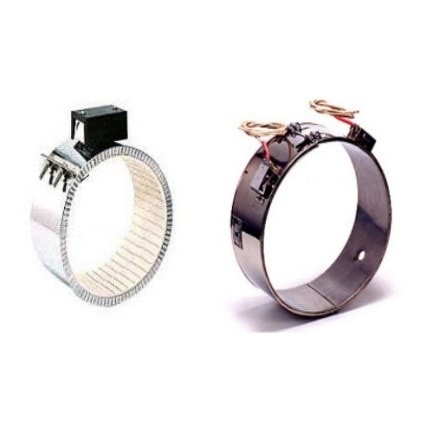
Ceramic Band on the left, Mica Band on the right
The most commonly used items for the application of heat within the Plastics Sector are heater bands. These ‘ring’ like products are clamped around hollow items such as the barrels of injection moulding and extrusion equipment. In conjunction with thermocouples (a form of temperature measurement) the heater bands are used to help maintain the correct working temperature of the molten plastic being processed.
‘Barrel Bands’ are now more commonly of the Ceramic type, rather than the older Mica design. This is because Ceramic bands are naturally more insulated (so more energy efficient), can provide a higher wattage density (more power is needed when working with some modern engineering polymer types) and have a longer service life.
Injection moulding machines are also fitted with Nozzle Bands, these being small, usually Mica type heater bands. These prevent material from ‘chilling off’ when being transferred from the output end of the plasticising unit into the rear of the mould tool.
Other commonly used heating elements include Cartridge Heaters, these cylindrical devices being easily inserted into a blind hole in the wall of a production tool. This electrical heating method can be used instead of or to supplement heating through hot water channels.
Visit Here to contact the leading UK companies that can provide you with advice and quotes for your heater bands & heater element requirements.
Light-weighting in this context is the reduction in weight of plastic components through the use of external technology. There are two common methods of achieving this result.
Material removal. Inert gas (Gas Assisted Moulding) or water is used to hollow out a core of material from within a component. Inside the mould tool, a solid piece of material will begin to solidify from the outside (closest to the cooling channels of the tool) inwards, creating an opportunity to expel molten polymer to create a hollow object.
Unlike when using a moving core to create an internal bore, gas or water can flow around bends. The process also helps to minimise the chance of surface ‘sinking’.
‘Foaming’ the material. Not to be confused with internal foaming as a result of a chemical reaction, the basic process involves the introduction of inert gas at the point of material injection into a mould tool.
Rather than removing material, a smaller shot weight of molten plastic is used, the introduction of very small bubbles then expanding the volume of plastic within the tool. The resulting moulding will still exhibit a perfect external skin of material (the process again reduces the risk of surface sinking resulting from shrinkage) but will weigh considerably less than typical. There should also be an associated improvement in production cycle time, as the volume of the material within the wall section is effectively reduced.
Mucell™ is an example of microcellular Foam injection moulding technology that is widely used in the automotive industry, where lightweighting is particularly important.
Metal fragments in plastic raw material (re-grind or virgin) are a common issue and can seriously damage plasticising components, block tool feed systems and contaminate end products.
Reprocessed material is more prone to metal contamination, particularly if the ‘end of life’ products required a degree of disassembly before recycling. (For example if they were constructed with mixed material types, or assembled with metal fasteners.)
There are two levels of technology associated with reducing the chance of metal contamination.

A typical ‘grid’ type magnet. The magnetic elements are contained within the metal tubes. In this example, baffles are used to direct material flow.
By assembling a grid (or ‘grate’) of magnetic elements that sit within a raw material flow channel/path, ferrous type metals can be captured. Some ‘rare earth’ magnets are powerful enough to attract particular grades of stainless steel. Softer metals such as Copper can still cause product contamination and blockages but are less likely to score or severely damage hardened plasticising components.
If for example, a machine hopper magnet is installed, it needs to minimise the gaps between its outer elements and the hopper’s internal wall. A round magnet won’t work well in a square hopper!
The spaces between rows of magnetic elements will determine how close a ferrous particle could ‘pass’. The bigger the distance, the lower the magnetic field strength, so tighter spacing, stronger magnets or baffles that guide material over the surface of the elements are all worth considering. Also, bear in mind that fast flowing material is more challenging to extract contaminants from, and if large flakes of regrind are being processed, too small a magnet can cause clogging.
Tip - If a material hopper tapers, the magnet will find the correct level. However, if it is too small, it may restrict material flow.
Metal Detection equipment can both detect and then remove both ferrous and non-ferrous metals. It can be designed to work with ‘free fall/gravity fed systems, under belt conveyors, or as a tunnel detector that surrounds material as it is conveyed.
Visit here to contact the leading UK companies that can provide you with advice and quotes for your magnetic and metal detection requirements.
Most clamping systems are used for the retention of injection moulding tools, i.e. to attach each half of the tool to the machine platens. The fixed platen has a central hole that is used to initially position the tool using a location ring that is permanently fixed around the tools injection point. Until the tool is clamped into position, the tool is usually held in position by an overhead crane or gantry.
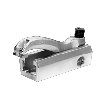
Image courtesy of Lenzkes Clamping Tools
Clamping by pressure using manual solutions. Injection moulding machines typically have a series of pre-drilled and threaded location holes in both platens. These allow a variety of tool sizes to be secured using metal clamps. (Tools usually have back plates that are slightly larger than the rest of the plates used in its construction). For most small and medium tonnage machines, four clamps per tool half are typical.
In some cases, platens also have machined T-slots. These allow T-nuts to be inserted, the clamps then bolting into these rather than fixed platen holes. This means that clamps can be slid into position quickly and easily and without the possibility of stripping a platen thread.
Clamping by pressure using powered solutions. With some very large machines, or when tool changes are extremely frequent, hydraulic clamps can be used. These are sometimes used in conjunction with automated tool change systems, as they can be activated by an external control system.
Magnetic Clamping. Magnetic platens affix to the front of the existing machine platens. They use electromagnetic force to quickly secure tooling and release it as required. The technology used means that a power cut will not release the tool.
Position Transducers use a coil or magnetic field to convert linear motion into a voltage, this then being translated by software into a physical measurement. They typically have a fixed body and either extending rod or external ‘shuttle’ that is affixed to the moving component. They are most commonly used in injection moulding machines, to monitor and control injection stroke, ejector position etc.
Pressure Transducers are used for three main functions.
These items are frequently used in conjunction if a standard injection moulding machine needs to be adapted for multi-material moulding.
Rotary Platens are permanently fixed to the front face of the machines fixed platen. The rotary platen and the half of the mould tool mounted to it are rotated to bring cavities within the tool into contact with different injection units. This allows different grades or colours to be added and permanently combined within a single production cycle.
The platens have rotary ‘unions’ that allow cooling water and hydraulic circuits to be connected with the tool.
Secondary Injection Units allow one or more additional polymer grades/colours (in addition to that provided by the moulding machine’s own injection unit) to be incorporated into a moulded product.
If a particularly small amount of plastic is involved, then the secondary unit may be compact enough to be directly mounted onto the mould tool. Due to their size, these units are frequently powered by a core pulling circuit provided by the moulding machine.
Larger secondary units are more commonly mounted directly onto the moulding machine (for example, vertically positioned on top of the fixed platen) or to the floor at 90 degrees to the machine. Larger units can be electrically powered or may have their own independent hydraulic power pack.
As secondary units have to be synchronised within the moulding cycle, they need to be either directly controlled by the moulding machine’s own electronic control system, or receive a timing signal from the machine via an interface. In the latter case, the secondary unit will need to have its own independent control system.
Visit here to contact the leading UK companies that can provide you with advice and quotes for your rotary platens & secondary injection unit requirements.
Testing may be on raw material or components. Examples include:
Visit here to contact the leading UK companies that can provide you with advice and quotes for your testing, measuring & scanning equipment requirements.
Apart from basic measuring equipment such as hand-held calliper type Verniers, plastic components may need to meet precise tolerances, particularly if they are to form part of a complex assembly. The equipment used is the same as for any other manufacturing sector. It includes:
Vision systems are now frequently employed to inspect components, even when they are not static. Moulding faults (such as short-shots) or missing components can be identified by the equipment, and either an alarm raised, or the suspect part automatically segregated.
Visit here to contact the leading UK companies that can provide you with advice and quotes for your plastic Testing & Measuring requirements.
Rather than melt plastic surfaces to allow them to combine physically, or introduce additional materials such as fasteners or adhesives, components can be joined by ultrasonic welding. This technique uses high-frequency sound waves (in the order of 20 MHz or higher) to ‘excite’ the polymer strands to the point that they can fuse together.
Two or more thermoplastic components are clamped together before a device called a horn (or sonotrode) focuses the sound waves at the required location. Depending on the design of the horn, the size and shape of the weld can be altered.
Visit here to contact the leading UK companies that can provide you with advice and quotes for your Ultrasonic Welding requirements.
In the plastics sector, vacuum components usually relate to component handling, e.g. for part removal from a moulding machine using a robot. The two main component groups are:
Weighing and counting equipment can be incorporated into a larger product handling system. For example, bag filling carousels can be fed by a conveyor that is transporting finished products away from the production equipment.
Weighing equipment can be used to either provide a packaged weight of the finished product or more frequently, a set number of packaged components. In the latter case, this is achieved by determining the weight of a single component, so that when, for example, 100 components have been added, the container is replaced with an empty one.
Sorting equipment most frequently takes the form of a sprue (runner) separator. This uses a rotating drum or paddle system to physically separate moulded components from their feed system, i.e. if both are ejected from the moulding machine together. Following separation, a conveyor may transfer the components to another station, for weighing and packing for example.
Visit here to contact the leading UK companies that can provide you with advice and quotes for your Weighing, Counting & Sorting equipment requirements.