
LINKING SERIOUS BUYERS TO THE BEST SUPPLIERS
Serving the UK & IE plastics industry
Injection Moulding Screws & Barrels
Injection Moulding Refurbishment Services
Extrusion Screws & Barrels
Extrusion Refurbishment Services
Tips, Valves, End Caps & Nozzles
With the exception of Vacuum Forming / Thermoforming, Rotational Moulding and Fabrication, plastic processing equipment relies on a Plasticising Unit to melt and deliver molten polymer.
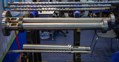
The two primary components of a plasticising unit are the screw and the barrel. The barrel is a hardened metal tube within which the screw is housed. At one end of the barrel will be the point of material entry, sometimes called a feed pocket or throat. The opposite end (the output end) is where the processed material has reached its fully molten state.
The Screw has a helical flight (like an Archimedes Screw), meaning that if it is rotated in the correct direction, the material will move forward. This is because the gap between the top of the screw flights and the inside diameter of the Barrel is very small, so the material cannot escape from the root of the screw. The root of the screw varies along the length of the screw.
Depending on the process, the barrel design will vary:
Injection moulding barrels have a single bore that runs directly along the centre. At the output end of the barrel will be either an internally threaded opening or a bolted on end cap that contains the internal thread. (The latter is more common with larger diameter units). This thread is designed to accept the male thread on an injection nozzle. The nozzle makes contact with the back of a mould tool so that molten plastic can be injected under pressure.
Barrels designed for continuous extrusion processes (blow moulding, pipe, and profile extrusion) tend to be longer but can also have two bores that overlap slightly, looking like a figure of eight when viewed from the front or rear. The screws are designed so that their flights and root sections mesh with each other. This creates a higher material throughput and superior mixing ability than achievable with single screw designs.
Twin-bore designs have two main variants – twin parallel and twin conical. In the conical design, the screws and barrel bores are of larger diameter at the rear and taper down towards the output end. This further enhances the mixing ability of the equipment, making it a popular design for material compounding lines.

As the screw rotates and material is fed forward, the screw is allowed to be pushed backwards, (the screw-back or recovery phase), this is caused by molten material collecting at the front end of the Barrel and applying reverse pressure to the front face of the screw.
To prevent this material from travelling back along the screw, a check valve is fitted to the front of the screw. (Commonly called a screw tip assembly).
The screw tip is made up of three components – the body, the check ring, and the pad. It is designed so that as the material passes to the front of the barrel, it can flow clearly under the check ring and through grooves cut into the nose of the body. When the material is then injected into the mould tool by a hydraulic or electrically powered ram, that pushes the screw
forward a precise distance, the ring is forced back against the pad, thus creating a seal that prevents material from flowing backwards.
An alternative design is a ball-valve. With this design, a large ball bearing rather than a check ring shuttles backwards and forwards to allow or stop material flow.
Particularly in the case of larger bore injection moulding barrels, the output end of the unit is too large to accept a threaded nozzle directly. Mainly because of the high cost associated with machining a nozzle with a very large rear thread. End caps are in effect an adapter that typically bolts onto the end of the barrel and has a female thread that creates a sealing face when a nozzle is screwed into place.
Injection moulding nozzles are used to transfer molten plastic between the output end of the plasticising unit and the entry point on the rear of the tool. (Sometimes called the sprue bush). They are usually fitted with heater bands to prevent the material from chilling and vary in length, e.g., to reach a sprue bush that is recessed into the rear of a tool.
The rear of the nozzle will have a point of material entry that is relatively large in diameter, to prevent material from hitting a 90-degree surface, and then tapers down. The output end of the nozzle will have a much smaller hole that is typically slightly smaller than the hole in the tool’s sprue bush. The nozzle’s tip will also ideally have a matching radius (or a slightly smaller radius) so that there is good contact between tip and bush.
Nozzles sometimes have differing internal profiles that suit a particular type of material. For example, to prevent ABS material from burning, a gradual internal nozzle taper can be used, this minimising shear heat.
Nozzles can be solid (machined from a single piece of steel) or have a removable tip. In the latter case, the end of the nozzle has a female thread and sealing face that can accept a range of threaded tips. In this way, tips can be changed to match a particular tool or to add an extension. Tips can also have differing internal profiles, e.g., a ‘reverse taper’ that reduces drooling when low viscosity materials are processed. Nylon is a good example.
Injection moulding and extrusion screws, barrels and components can be produced from existing drawings or by using sample components as a reference. Prices are often more competitive than OEM's. It is also sometimes possible to improve the design in terms of durability and the ability to process a specific material type. For example, some OEM's supply machines with nitrided barrels fitted. Although the internal bore is extremely hard-wearing, the layer of hardened material is also relatively thin. By contrast, the bi-metallic barrels available from both the OEMS’s and our UK based specialists have a much thicker layer of hardened material and offer a longer and more consistent service life