LINKING SERIOUS BUYERS TO THE BEST SUPPLIERS
Serving the UK & Irish plastics industry
End of Arm Tooling
 (1).png)
Sprue Pickers
.png)
Beam Take Out Robots
.png)
Side Entry Robots & IML
 (1).png)
Six Axis & Collaborative Robots
Automation Systems
.png)
Machine Safety Guarding
.png)
Vacuum Pumps & Systems
Vision Inspection Systems
Robots & Automation Services
 (1).png)
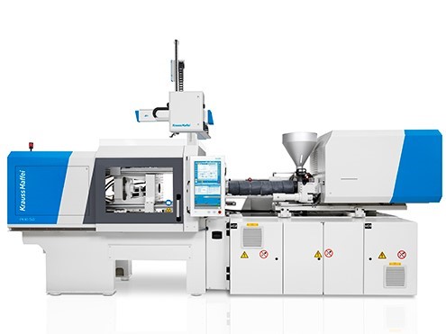
The term automation covers a wide range of scenarios, from simple de-moulding cells to complex assembly lines. Within the plastics sector, the majority of automation is designed to reduce labour costs, prevent damage to parts and provide consistent production rates. This is achieved by replacing machine operators with programmable robots that are controlled and synchronised by the production equipment.
Automation is now extensively used in injection moulding, as it usually involves 24/7 production.
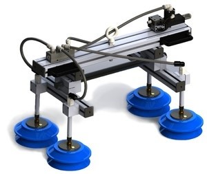
End of arm tools (EOAT), sometimes also known as grippers are the devices that allow a robot to interact with a moulded component.
Vacuum systems
In their simplest form, one or more suction cups are used to collect an item from the face of an injection mould tool. This example of part collection requires a flat and preferably smooth surface to attach to.
If several cups are needed because of component weight, or to stop flexing and loss of suction, a plate or adjustable frame is used to support the cups. To prevent heavy contact with the component being collected, cups are frequently mounted on the end of spring-loaded posts.
Suction cups require a vacuum to be generated, typically using a vacuum generator. Sometimes called a vac circuit when supplied as an integrated part of a robot, vacuum generators use a compressed air supply to generate a vacuum. A network of small plastic tubes connects the vac generator to the suction cups.
Modern systems can save energy by only applying a vacuum when it is needed. Older systems continuously suck in air when no component is in place to seal the circuit.
It is also possible to detect when a part is not present because air begins to flow in the circuit. This can be used to generate a signal that stops both the robot and the machine from cycling. This can prevent an injection moulding machine from ‘closing over’ when a component is still present on the face of the tool.
Gripper systems
End of arm tools can also employ mechanical devices to grip components physically. A typical application is the handling of sprues or runner systems, the main component being secured using suction cups, for example.
A blow circuit is a pneumatic supply fitted with a solenoid valve, which is controlled by the robot, causing the device to actuate. Grippers can be single-acting, using air to actuate and a spring to return, or double-acting, utilising air for both movements. A sensor can also be incorporated for component detection, if required.
Pneumatic pliers are the most common type of mechanical gripper and vary in design, by having gripping or padded surfaces to provide purchase on the component.
Finger grippers work differently, in that they only have a single moving arm. These grippers are designed to tuck behind a component to help secure it or pull it from the face of a mould, if it has a tendency to stick.
Sprue pickers (also known as swing-arm robots) are small and less complex servo/pneumatic robots that are most often used to remove a sprue/runner system from a mould tool. This is a cheaper alternative (to, e.g. linear robots) for smaller machines that are run fully-auto, but have a sprue or runner that doesn’t come away with the moulding or can’t be mixed in with the mouldings.
The robots are typically fully contained within the guarding of an injection moulding machine and arc into position when the tool opens. They are typically fitted with a pneumatic gripper that grasps the sprue or runner, before moving back out of the moulding area. The gripped item is then dropping into a storage container or the intake hopper of a beside-the-press granulator.
Also known as cartesian and beam robots, these are usually mounted on the machine’s fixed platen. The size and payload of the robots vary, increasing with the size of the machine being served. The vast majority of modern units have three servo-driven main axes, plus a pneumatic ‘wrist’ that can flip a component to make it easier to place flat on a conveyor belt.
When the tool opens, the robot extends down into the space created, then forward towards the moving platen. A device called an End of Arm Tool then attaches to the moulded product. This is most frequently achieved using suction cups, but mechanical grippers are sometimes used. The robot then backs away from the tool and moves vertically upwards so that the component clears the top of the machine door. The part is then moved horizontally (90 degrees to the plane of the machine, usually on the opposite side to the machine controller) before being lowered and placed onto a flat-bed conveyor. Robots typically have a ‘wrist’ action, allowing the part to be flipped 90 degrees if this provides a more stable orientation.
The robot movements are usually programmed by a stand-alone hand-held pendant, the programme differing slightly for each product. The robot is controlled by the machine using an interface, the industry standard being either Euromap 12 or 67. (67 is becoming the industry standard). This ensures that the robot moves at the correct times within the machines cycle, as well as tying in safety mechanisms that prevent misuse and injury.
In turn, the robot usually controls the conveyor belt, causing it to index forward a set amount as it is filled.
As the name suggests, these robots are typically mounted at 90 degrees to the moulding machine, but at a height that is in line with the mould tool. These high-speed robots operate with the machine door permanently open (externally guarded) and usually only have two-axis. They are often used in conjunction with other specialist equipment, for example, to provide in-mould labelling of products or to stack products before packaging. Typical applications are the high-speed production of thin-walled packaging products.
In-mould labelling is a technique that in effect, moulds a plastic component onto its label, creating a much stronger bond than achieved using adhesives. The most common application is the labelling of thin-walled packaging items such as paint containers.
Originally made of paper, most modern labels are made from PP or PS, making the final product easier to recycle.
As the name suggests, a label is placed onto one surface of a mould tool, usually using a side-entry robot (because of its high speed) that may also remove the product moulded and labelled in the previous cycle. The tool closes, and the next product is moulded.
The label usually sticks to the face of the tool through the application of an electrostatic charge or vacuum, preventing it from dislodging due to both gravitational force and the momentum of a fast cycling tool.
Labels are supplied by specialist printing companies, usually on large reels. Labels are dispensed and presented to the robot’s end of arm tool by specialist equipment.
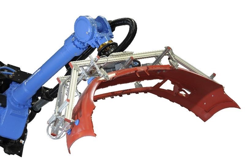
Sometimes called industrial robots, these more complex robots are better able to mimic the human arm, making them ideal for more complex tasks. They are also extremely accurate, so can, for example, place metal inserts into a mould tool so they can be over-moulded.
These robots are generally mounted on the floor but in many applications they are mounted onto the machine platen.
As they can be floor mounted, they also work well in factories that have a restricted head height. They are typically mounted on the opposite side of the machine to the machine’s control interface, with the rear door of the machine permanently open. External guarding is used to provide access with safety interlocks.
The machine and robot communicate via a Euromap 67 robot interface. Sometimes parts are de-moulded and placed directly onto an indexing or continuous conveyor that exits the guarding. It is also possible for the robot to carry out secondary operations such as assembly or part labelling during the moulding cycle.
A simple automation cell typically consists of a robot within a guarded area, plus a flat conveyor belt that carries the de-moulded (removed from the mould tool) components through an opening in the guard. Robots are fitted with a device that aids part removal (an End of Arm Tool), either using a vacuum system or a pneumatic gripper.
More comprehensive automation cells can involve multiple robots and secondary operations including bowl feeding, product assembly, testing, painting, printing and labelling, etc.