LINKING SERIOUS BUYERS TO THE BEST SUPPLIERS
Serving the UK & Irish plastics industry
UK & IE Injection Mould Toolmakers
Extrusion Dies & Dieheads
Blow Mould Toolmakers
Fast Cycling & Packaging Mould Toolmakers
Twin Shot Mould Toolmakers
Medical Mould Toolmakers
Thermoset
& Compression Mould Toolmakers
Micro Mould Toolmakers
Large
Volume Injection Mould Toolmakers
3D Printed Mould Toolmakers
Prototype Toolmakers
Hot Runner Systems & Controllers
Mould Components & Accessories
Repairs, Refurbishment & Polishing Services
Mould Texturing & Engraving
Rotary
Platens &
Secondary Injection Units
Injection moulding a product is not possible without the appropriate mould tool or group (suite) of tools. The tool is fitted into a suitable size of injection moulding machine, based on both the physical size of the tool and the clamping force required to keep the tool fully closed when the material is injected under high pressure.
The tool has two halves, one attached to the fixed platen and the other the moving platen of the moulding machine. At the most basic level, one half of the tool contains a core (male) and the other a cavity. The void between core and cavity is where the molten plastic is injected and then solidifies to form the required component. Water channels within the wall of the tool are used to control and accelerate the cooling process.
Tools can have more than one impression, i.e., they have several cores and cavities. When these are exact copies, the common terminology used is multi-impression tooling. When several different components are produced, this is termed a family tool.
Mould tools are constructed from a series of mould plates and spacers. Back-plates (bolsters) are used to clamp each half of the tool to the moulding machine’s platens. (These tend to be slightly larger to allow easier clamping). The tool is built up using additional mould plates into which the core and cavity are machined.
Risers (spacers) are used to create gaps between plates, for example, to accommodate a moving ejector plate mechanism. Guides (dowels) are frequently used on one half of the tool, these mating with female bushes in the other half of the tool to ensure correct alignment and increased strength during the closing process.
The rear face of the fixed half of the tool also contains a sprue bush, this being accessible via a central hole in the injection moulding machine’s fixed platen. The sprue bush is a round plate with a radiused depression containing a central hole that runs to the mould cavity. The nozzle of the injection moulding machine is pushed (using a set amount of pressure) against the bush to create a leak-free seal. This relies on the nozzle having a matching radius and orifice size, to allow the plastic to be injected into the mould tool without material loss.
Tool mould plates are available in a variety of metal types and grades. Aluminium plates are typically used for less demanding prototyping or low volume production, especially if polymers don’t contain abrasive fillers. Pre-hardened steel plates provide a shorter lead-time and are suitable for medium to high volume work, while tool steel grades have to be hardened after they are fully machined, but provide the ultimate level of durability.
Where more complex plastic parts are being moulded, additional mechanical items such as moving side cores are sometimes required. These move into and out of the mould's cavity to create features such as holes in the side of a moulding. This movement can be achieved in two ways.
Tools can have a single impression (one matching cavity and core), produce multiple identical mouldings at a time (multi-impression tools) or a group of non-identical mouldings (family tools). Single impression tools frequently have one central material injection point, although mouldings with a large surface area or long material flow length may benefit from several material injection points.
When it is necessary to distribute molten plastic to several injection points on a single moulding, or multiple individual cavities, this is achieved via a runner system. There are two common types of runner systems.
In some cases, injection moulding tools need to meet particular requirements, so can be manufactured by toolmaking companies with specialised knowledge and equipment. Some examples are given below:
Fast Cycling & Packaging Moulds
Fast cycling tools are characterised by four main criteria:
Visit here to view the leading UK companies that can provide you with comparative quotes for Fast Cycling & Packaging Moulds.
Multi-Material & Twin Shot Moulds
Specialist tools are required when two or more material grades or colours are combined into a single product. This requires them to have more than one material feed system, the position of each material entry point matching the design of the moulding machine.
The most common variation is for twin shot (2K) moulding, where the injection moulding machine has a primary horizontal plasticising unit that typically injects the highest volume of plastic into a central sprue bush on the back of the tool. A smaller secondary unit injects a smaller amount of material via a second sprue bush served by an injection unit that is 90 degrees to the primary unit, or sometimes mounted above the primary unit (piggy-back unit).
There are different methods used for injecting each material in sequence:
Visit here to view the leading UK companies that can provide you with comparative quotes for Multi-Material & Twin-Shot Moulds.
Medical Moulds
Medical moulds are required to match the requirements of the environment in which they are intended to operate. Most commonly, this involves an injection moulding machine within a cleanroom environment.
As well as typically being manufactured using grades of steel developed specifically for medical device production, care is taken to minimise product contamination. Examples of this would be the use of lubricants that are formulated for this type of application, or tooling designs that minimise the chance of contact with lubricants.
Companies that specialise in the manufacture of medical moulds are also involved with the tooling validation process. As well as the usual tool trials and product verification through measurement, validation also ensures compliance to standards developed specifically for medical device production. In some cases, validation takes place on the premises of the toolmaker, using dedicated moulding machines that are sometimes themselves operating within a cleanroom environment.
Visit here to view the leading UK companies that can provide you with comparative quotes for Medical Mould Tools.
Thermoset & Compression Moulds
Thermosetting materials have a tendency to be particularly abrasive, so tooling is produced using hardened tool steels that may also have a protective coating applied, e.g. chrome.
Tools are also required to be heated to higher temperatures than those used for typical thermoplastic grades. The use of water channels is not possible, so either oil is used (as oil can be heated to much higher temperatures than water), or electrical heating elements are embedded within the walls of the mould.
Thermoset materials also tend to have a very low viscosity in their molten state. For this reason, particular care is taken when machining mating surfaces to minimise the potential for ‘flashing out’.
Compression moulding is usually performed using simple tools that are fitted to vertical presses rather than injection moulding machines. They are manually filled or ‘dosed’ with thermosetting materials, so don’t require a material feed system. They do, however, need to be resistant to abrasive fillers and be able to operate at high temperatures.
Visit here to view the leading UK companies that can provide you with comparative quotes for Thermoset and Compression Moulds.
Micro Moulds
As a rule of thumb, micro moulds should be capable of producing mouldings that weigh less than one gram. They are designed to run on specialist injection moulding equipment that has the required accuracy.
Despite the small nature of the mould cavities involved, components can be relatively complex in design, e.g. small gears and cogs. For this reason, companies that specialise in the manufacture of micro moulds have to use CNC equipment that is capable of working on a small scale and with high levels of accuracy and resolution.
Visit here to view the leading UK companies that can provide you with comparative quotes for Micro Moulds.
Large Volume Moulds
Large plastic items such as some automotive components (bumpers for example), larger drainage products, wheelie bins and storage crates require much larger than typical mould tools. These weigh in the order of ten tonnes and above and are therefore difficult to both handle and manufacture.
Companies that specialise in larger mould tools are equipped with heavy-duty lifting equipment and CNC machinery with very extensive working envelopes.
Visit here to view the leading companies that can provide you with comparative quotes for Large Volume Injection Moulds.
More often called extrusion dies, these are used to convert the rod-like output of plastic from an extruder into the required shape. This can involve a lot of stress on the material as it is distributed through the flow channel of the die, so there are several design considerations
The plastic profile design. Sharp corners, very large hollow areas and large variations in wall thickness can make it difficult to produce a consistent profile. Wall thicknesses are probably most critical, as the material will flow faster through thicker sections than thinner ones.
Design of the Extrusion Die. This should ensure that:
Correct Profile Dimensions. It should be noted that the shape and the size of the finished extruded product may be dimensionally different from that of the die flow channel. This is because:

Blow moulding uses a split tool that is similar to that used in injection moulding but has no core, just a cavity or multiple cavities. Although relatively simple in design, there are still several critical factors to be considered.
Injection Stretch Blow Moulding. Injection Stretch Blow Moulding is often used to make PET bottles and is a two-stage process that involves pre-forms to be injection moulded in advance. There, therefore, also needs to be a multi-cavity injection moulding tool.
As vacuum forming and thermoforming are relatively simple production methods, the mould tools are also simple in design. In essence, they are a male shape over which a hot plastic sheet is draped. In the case of vacuum forming, a negative pressure is generated below the sheet, drawing it downwards on to the mould. This can be assisted by having numerous small holes through the mould that aid in the extraction of air.
Materials used depend largely on the length of production run (for reduced wear) and cost limitations. The cheapest moulds are often made of wood, followed by composite moulds made from resin. For a better finish and prolonged lifespan, cast or machined aluminium tools are the norms.
Rotational Moulding tools are hollow and relatively simple, typically comprising of two halves that are clamped together once the powder has been loaded. If products are difficult to extract, then sometimes three-piece tools are required. Joints need to be tight to avoid leakage.
The majority of small to medium products are produced using cast aluminium tools, while sheet steel fabrication is preferred for large products.
Design considerations include:
Most types of tooling (not usually vacuum forming) benefit from having water circuits that surround the core and cavity of the tool. These circuits can carry either heated or chilled water, depending on the application. It isn’t uncommon for one half of an injection moulding tool to be heated and the other cooled.
It is fairly common practice for the tools to have numerous water circuits, i.e. there is an entry point for water and an exit point that transfers the water back to the heating or cooling device.
General rules to follow are:
Water Fittings
To speed up the process of piping up a tool, it is common practice to use quick release water fittings. These consist of a male and female half that lock and seal when engaged. They are released via an outer moveable ring (sleeve) that slides up and down the larger diameter female component.
You should be aware that several manufacturers produce these fittings, each having a unique design that is not interchangeable.
The male half is fixed into the tool using a male thread (the tool has the matching female thread) that is usually BSP in form. (1/4” and 1/8” BSP are the most common).
The female half is typically terminated by a hose-tail, a pipe with outer raised ridges that is pushed into the correct size I.D. rubber hose. This connection is made secure by using an adjustable hose-clip.
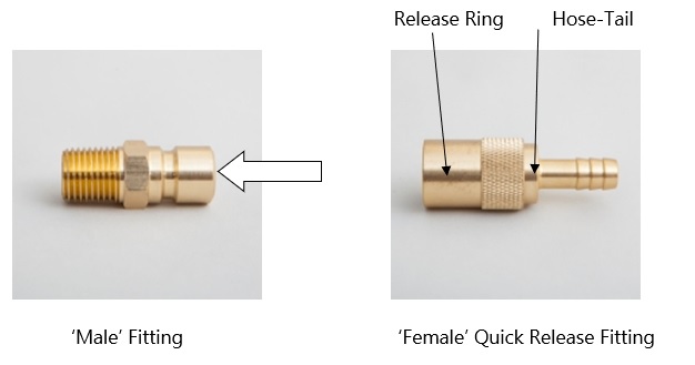
Variations of the male quick release half include those with or without a shut-off valve that forms a seal when the female half is uncoupled. The valve is designed to minimise water leakage and also prevents air from entering the tool during storage, thus minimising corrosion. The drawback of this feature is that water flow is impaired in comparison to flow-through units.
Female couplings are typically available with either butyl or Viton seals, the latter being better suited to higher temperature applications.
Hot runners are frequently used within injection mould tools when it is desirable to not have a solid runner system or sprue. This could be for several reasons-
Hot Runner systems work by keeping the material within the feed system of a tool in a permanently molten state through precise temperature control. This is achieved through heating elements and thermocouples. The feed is then ‘pinched off’ at the point of entry into the moulded component, before its removal from the tool, leaving just a small pip of material.
Hot Runner Controllers are the devices that monitor and regulate the temperature of each hot runner zone. They can be set at a precise temperature to suit a particular material and to help adjust flow rates. They then maintain the correct temperature by using thermocouple output to calculate actual zone temperature and then supply power to the associated heating elements as required.
Controllers vary in complexity, ranging from single zone portable units to 48 zones or higher, e.g. for caps and closure tools. Controllers are also sometimes used to control the temperature of a heated sprue bush, preventing premature ‘chilling off’ of material entering a mould tool. In some cases, a hot runner zone will be used to control more than one mould cavity, particularly when large numbers of low complexity products are involved.
If you aren't familiar with SMED, this stands for Single Minute Exchange of Die and centres around reducing downtime. A good example within our industry would be the regular tool change of an injection moulding machine.
As well as improve machine efficiencies, SMED can also make it practical to supply on a J.I.T. basis, therefore offering the potential to win additional business. Below are some effective and relatively lower-cost options for you to consider.
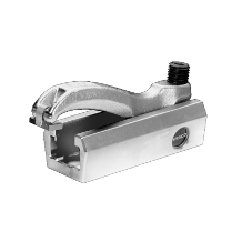
Quick Clamping systems
Easy to use clamping systems such as the ones supplied by PlastikCity Partner company Lenzkes are a good starting point. The clamps come with platen bolts as well as T-nuts, the latter being ideal if your machine has slotted platens. The bolts and T-nuts are supplied according to Euromap standards for the platens fitted to particular sizes of machine.
You can also speed up change over times by trying to standardise backing plate sizes for tools that run in a particular machine size.
There are numerous more expensive quick clamping systems such as Magnetic platens, hydraulic clamps and bayonet clamping.
Magnetic platens affix to the front of the existing machine platens. They use electromagnetic force to secure tooling and release it as required. The technology used means that a power cut will not release the tool.
Hydraulic clamps use hydraulic pressure to hold the tool in place. They are typically used with very large tooling and form part of an automated tool-change system that uses roller systems to move tools into position. The tools are then hydraulically clamped, there usually being backup systems to prevent accidental tool release. These automated systems also tend to have systems for automatically connecting oil and water circuits.
Scheduling of tools
Planning of the sequence of jobs you run should also be a major consideration. There is no point investing in expensive automatic tool changing systems, but then run two alternating tools with polymers that have vastly different processing parameters. Five minutes to change the tool, but a good hour for a material change and to get the barrel to the right temperature!
It isn't however always practical to plan your tools to run in a particular order, so purging agents should be a consideration, especially as some can also be used to clean a tools runner system. A selection of proprietary brands can be found in the PlastikCity Purging Agent category.
Reducing setting up time for tools
With many companies now operating machines with the ability to store numerous tool settings, a good proportion of tool setting time is often taken up by the 'piping up' of waterways.
Hard piping is a cheap and easy solution that saves having to hunt around for the right hoses and fittings. It is also a much tidier solution and prevents miss-connections of hot and cold circuits and the overuse of 'looped circuits' that can 'starve' a tool of sufficiently cool water.
A simple form of hard piping can be achieved quickly and cheaply by using 90-degree hose-tails, flexible hose and tool mounted manifold blocks. The manifolds are typically mounted in colour-coded pairs, with one pair on each half of the tool. If there are water fittings on the underside of a tool, then small feet can provide clearance.
If large quick release fittings are used to connect to the manifolds once the tool is in situ, water connections can be completed in seconds. You can also pre-heat a tool using a spare water/oil heater.
You can ensure the right connections are made by using different types of connectors, e.g. D.M.E. units from the water heater to hot tool circuit, Staubli for chiller circuit etc. All the necessary components can be sourced from Mould Shop Consumable specialists.
Having tools stored near a machine, and raw material to hand (preferably already dried if required!) are also key points to consider.
Most clamping systems are used for the retention of injection moulding tools, i.e. to attach each half of the tool to the machine platens. The fixed platen has a central hole that is used to initially position the tool using a location ring that is permanently fixed around the tools injection point. Until the tool is clamped into position, the tool is usually held in position by an overhead crane or gantry.
Clamping by pressure using manual solutions. Injection moulding machines typically have a series of pre-drilled and threaded location holes in both platens. These allow a variety of tool sizes to be secured using metal clamps. (Tools usually have back plates that are slightly larger than the rest of the plates used in its construction). For most small and medium tonnage machines, four clamps per tool half are typical.
In some cases, platens also have machined T-slots. These allow T-nuts to be inserted, the clamps then bolting into these rather than fixed platen holes. This means that clamps can be slid into position quickly and easily and without the possibility of stripping a platen thread.
Clamping by pressure using powered solutions. With some very large machines, or when tool changes are extremely frequent, hydraulic clamps can be used. These are sometimes used in conjunction with automated tool change systems, as they can be activated by an external control system.
Magnetic Clamping. Magnetic platens affix to the front of the existing machine platens. They use electromagnetic force to quickly secure tooling and release it as required. The technology used means that a power cut will not release the tool.
These items are frequently used in conjunction if a standard injection moulding machine needs to be adapted for multi-material moulding.
Rotary Platens are permanently fixed to the front face of the machines fixed platen. The rotary platen and the half of the mould tool mounted to it are rotated to bring cavities within the tool into contact with different injection units. This allows different grades or colours to be added and permanently combined within a single production cycle.
The platens have rotary ‘unions’ that allow cooling water and hydraulic circuits to be connected with the tool.
Secondary Injection Units allow one or more additional polymer grades/colours (in addition to that provided by the moulding machine’s own injection unit) to be incorporated into a moulded product.
If a particularly small amount of plastic is involved, then the secondary unit may be compact enough to be directly mounted onto the mould tool. Due to their size, these units are frequently powered by a core pulling circuit provided by the moulding machine.
Larger secondary units are more commonly mounted directly onto the moulding machine (for example, vertically positioned on top of the fixed platen) or to the floor at 90 degrees to the machine. Larger units can be electrically powered or may have their own independent hydraulic power pack.
As secondary units have to be synchronised within the moulding cycle, they need to be either directly controlled by the moulding machine’s own electronic control system, or receive a timing signal from the machine via an interface. In the latter case, the secondary unit will need to have its own independent control system.
Visit here to contact the leading UK companies that can provide you with advice and quotes for your rotary platens & secondary injection unit requirements.
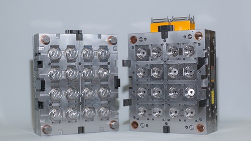
Basic Mould Tool Construction
Mould tools are constructed from a series of mould plates and spacers. Back-plates (bolsters) are used to clamp each half of the tool to the moulding machine's platens. These tend to be slightly larger to allow easier clamping. The tool is built up using additional mould plates into which the core and cavity are machined.
Risers (spacers) are used to create gaps between plates, for example, to accommodate a moving ejector plate mechanism. Guides (dowels) are frequently used on one half of the tool, these mating with female bushes in the other half of the tool to ensure correct alignment and increased strength during the closing process.
The rear face of the fixed half of the tool also contains a sprue bush, this being accessible via a central hole in the injection moulding machine's fixed platen. The sprue bush is a round plate with a radiused depression containing a central hole that runs to the mould cavity. The nozzle of the injection moulding machine is pushed, using a set amount of pressure, against the bush to create a leak-free seal. This relies on the nozzle having a matching radius and orifice size, to allow the plastic to be injected into the mould tool without material loss.
Tool mould plates are available in a variety of metal types and grades. Aluminium plates are typically used for less demanding prototyping or low volume production, especially if polymers don't contain abrasive fillers. Pre-hardened steel plates provide a shorter lead-time and are suitable for medium to high volume work. In contrast, tool steel grades have to be hardened after they are fully machined, but provide the ultimate level of durability.
Specialist components
Tools can contain specialist items, some common examples of which are given below:
HYDRAULIC CORES & LOCKING CYLINDERS. Where more complex plastic parts are being moulded, additional mechanical components such as moving side cores are sometimes required. These move in and out of the mould's cavity to create features such as holes in the side of a moulding. This movement can be achieved in two ways:
Using the action of the tool opening and closing to actuate slides/cams that generate the lateral movement. The advantage of this solution is that providing linkages aren't damaged; there are no timing issues that could result in the tool closing when a moving core is not retracted.
Using hydraulic cylinders to actuate the core movement. (Generally called hydraulic core pulling). This negates the need for complex mechanisms within the tool, but an external hydraulic circuit is needed. This is most commonly provided and controlled by the injection moulding machine. In the case of all-electric machines, a separate servo-powered hydraulic power-pack is controlled by the moulding machine. Additional safety measures are sometimes recommended, e.g., a photo-cell that can detect that the moving core is fully retracted before mould closing commences.
LOCKING CYLINDERS are designed to hold far higher forces than conventional cylinders, without the need to maintain hydraulic pressure.
COLLAPSIBLE CORES are specialist items that can create a void within a plastic component that is larger than would typically be possible. This is because once the moulding has been formed, the core both retracts and reduces its external measurements at the same time.
DATE STAMPS. Many plastic components have to be fully traceable for many years. One way to achieve this is through a round insert placed within the cavity of the tool, that carries a date mark. The year and month of production are shown using a system of adjustable rings and pointers.
EJECTOR PINS. In their simplest form, ejector pins are hardened steel dowels that slide through holes in the tool to assist the removal of moulded components. They can be supplied with hardened sleeves that act as a bearing and support structure.
As well as round pins, flattened 'blade' like pins are sometimes used, particularly if pressure is to be applied to the edge/wall of a component. Sleeve ejectors (where the outer sleeve moves and the centre is static) are also used to apply pressure over a wider surface area, or for example when a component is a hollow item such as a tube.
HOT RUNNER SYSTEMS. There is a dedicated section for 'Hot Runner Systems & Controllers'.
Prototype mould tools are used during the design and development stage of a project. They are the preferred option when prototype items need to be produced in the same material as the final mass-produced product, e.g. for testing purposes. They can be of much simpler construction than full production tools, for example, lacking water circuits or ejector systems.
Because only short production runs are needed, prototype tools can be made from softer materials that aren't hardened in any way. Aluminium tools are common, with naturally harder grades used if production runs are to be longer. Aluminium is good for dissipating heat (so no water circuits needed) and is quick and easy to machine.
If production runs need to be longer, you can add water circuits and ejector pins. Sometimes, harder tooling grades can allow the production of several thousand parts, although abrasive materials can shorten this significantly. This type of tooling is sometimes called bridge tooling, as it bridges the gap between prototype tooling and full-production tooling.
3D Printed tools are also a good option for very short production runs. They can be produced quickly, and modifications can be easily implemented; you just modify the CAD model and print another tool. These tools are really printed impressions (cavities) that are inserted into metal bolsters. The assembled unit is then mounted in a conventional moulding machine.