LINKING SERIOUS BUYERS TO THE BEST SUPPLIERS
Serving the UK & Irish plastics industry
LINKING SERIOUS BUYERS TO THE BEST SUPPLIERS
Serving the UK & Irish plastics industry
Plastic ancillary equipment are those most directly linked to primary processing equipment. Without these specialist pieces of support equipment, the production machine wouldn’t correctly function. Ancillaries vary from individual items (e.g. a material hopper loader) through to complete material feed systems that deliver different materials to machines around the production unit.
Ancillaries can be grouped into seven main categories, as seen below:
Conveyors used in plastic manufacturing environments are generally belt conveyors. Flat-bed conveyors are typically used in conjunction with robots. The robots ‘pick’ and ‘place’ components onto the belt, within a guarded area. The belt can either run at a continuous rate or can be set to index forward a set amount when sent a signal from the robot. Sensors are sometimes employed to ensure that the previously deposited item has moved clear, and to sense if the conveyor belt is at capacity.
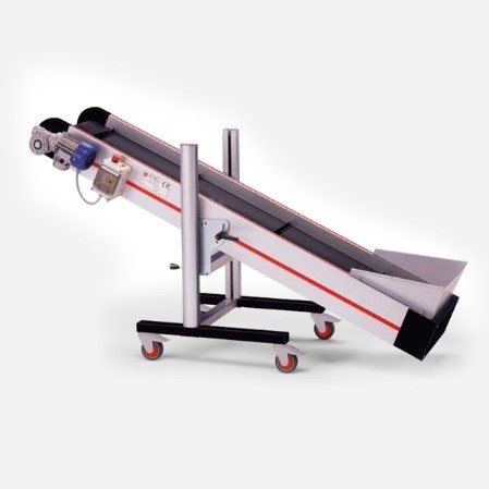
Image courtesy of Jenco Controls
& Export Ltd
Incline conveyors are generally used to remove products from underneath a production machine, i.e. when they free-fall from the production tool.
The belt usually has a series of raised flights designed to stop products from rolling back down the incline.
At the input end (lower) of the conveyor, it is common to have a feed hopper that prevents falling components from bouncing clear of the belt.
At the output end of the conveyor, particularly if there is a horizontal section, a sprue separator may be added. Sprue separators are most commonly used in cases where a material runner system is also present, preventing the need for manual sorting.
Variants include:
These systems consist of multiple conveyors. These provide a continuous loop that enables the transportation of materials around a production plant or other facility. The materials used for belt manufacture can be specified, depending on hygiene requirements, the temperature of product, etc.
This equipment usually works in conjunction with standard conveyors and is designed to reduce labour and improve accuracy. Functions include sprue/runner separation, component weighing or counting, boxing or bagging and temporary storage.
Separators are typically situated at the output end of a conveyor, either directly attached to the frame, or free-standing in the case of larger units. They are designed to remove the need to manually separate moulded plastic products from any runner systems or sprues.
Rotating paddles or rollers are used to achieve this task. In the case of conveyor mounted units, paddles are the most common solution. The gap between the rotating angled paddle blades and the upper surface of the conveyor belt is set so that either the moulding or the unwanted item is swept to the side and into a separate container.
Free-standing units most frequently use one or more adjustable rollers to achieve the task of separating mouldings from runners or sprues. They usually have a feed hopper mounted above the rollers to channel components as they fall from the output end of an inclined conveyor.
A cooling unit is designed to be fed by the output end of an inclined conveyor. It is most frequently used to rapidly reduce the temperature of plastic mouldings produced with short cycle times, e.g., caps and closures.
Mouldings are evenly cooled so that they are less likely to distort once moulded and deposited in a storage container. A rotating drum and fans are frequently used to achieve this.
The unit may also sometimes be fitted with inspection cameras that can detect faulty components.
Visit here to contact the leading UK companies that can provide you with advice and quotes for your plastic part conveyor requirements.
Material handling relates to the handling and processing of plastic raw material rather than finished components.
Material conveying equipment relates to the transfer of plastic granules (or regrind) from material storage to either an intermediate piece of equipment (such as a drying station) or directly to a production machines material inlet (hopper).
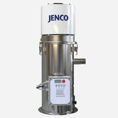
Image courtesy of Jenco Controls
& Export Ltd
Hopper loaders are used for transferring plastic raw material. This may involve transfer from a material storage bin to a machine in-feed hopper, or to and from a material drying station.
Single-phase units are usually used for low to medium duty applications and use a vacuum to draw material up to the machine material hopper.
Heavier duty three-phase units are often used where higher rates of material transfer are involved, movement is over larger distances, or material is difficult to handle. They are often mounted at floor level, pumping (blowing) material rather than using a vacuum.
A central material feed system, also known as a plastic material handling system, allows the polymer to be automatically distributed to processing machines; such as injection moulding machines and extruders, sometimes over long distances. Material is transported through a series of solid pipes using a centrally positioned vacuum pump.
Vacuum receivers (hopper loaders) on all machines are linked via a central control system that enables any machine to process any material without the need for human intervention. Material is generally sited away from the production area. Drying, blending and scrap reclaim can also be integrated into a central feed system.
Visit here to contact the leading UK companies that can provide you with advice and quotes for your material handling requirements.
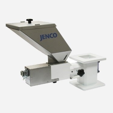
Image courtesy of Jenco Controls & Export Ltd
Material dosing units are used for adding a set amount of a single additive (a fixed percentage of colour masterbatch, for example) to a base raw material. Units are typically located between the main material in-feed hopper of a machine and the throat of the machine. Cheaper volumetric units use a small auger type screw that runs for a set amount of time at a constant speed. More accurate gravimetric units work by weighing the additive before depositing it into the machine throat.
Liquid colour feeders are used to dose liquid colour rather than solid pelletised masterbatch. The most common type of unit uses a peristaltic pump to force liquid colour along a thin, flexible plastic tube that terminates directly above a processing machines material feed throat.
The feed tube needs to have a very narrow bore, as liquid colours are highly concentrated and only small volumes are added. A low volume per second delivery rate allows a prolonged delivery time, ensuring an even mix within the processing machine’s plasticising unit. The speed of the pump can be regulated to achieve the required delivery rate.
It is also possible to fit a pre-mixing device above the processing machine feed throat that mixes the base material and liquid colour to make sure there is even dispersion.
Gravimetric blenders can be specified to weigh and also mix several additives into the primary raw material. These units are typically machine mounted and have a number of hoppers, one for each additive and one for the primary material. Once each component has been weighed and collected in a chamber, it is mixed by a rotating paddle.
Gravimetric batch blenders can be specified to weigh and also mix a number of additives into the primary raw material. These units are typically machine mounted and have several hoppers, one for each additive and one for the primary material. Once each component has been individually (sequentially) dosed and weighed within a collection chamber, it is mixed by a rotating paddle before being released into the processing machines feed throat.
This is a cyclical process, so is best suited to equipment that also has a production cycle rather than a continuous process. Injection moulding would be a typical application.
Loss-in-weight blenders are a type of gravimetric blender that is a better solution for continuous processes such as plastic extrusion.
Each material hopper is mounted on its own load cell and has a dosing auger. A computer monitors the reduction in weight of each hopper and adjusts the speed of each auger’s rotation to maintain the correct flow rate. A static mixer combines the different materials as they flow through the mixing chamber and into the feed throat of the processing machine.
Extrusion control blenders combine both gain-in-weight and loss-in-weight gravimetric blending technology. Individual materials are sequentially deposited into a weighing/mixing chamber, providing the highest levels of dosing accuracy. The chamber has a loss in weight load cell that then monitors the rate that material is taken up by the production line. In effect, the output of the production equipment (typically an extrusion line) is used to adjust the output of the blender.
Visit here to contact the leading UK companies that can provide you with advice and quotes for your material dosing & blending requirements.

Image courtesy of Jenco Controls & Export Ltd
Storage bins for holding plastic material in the vicinity of a processing machine can be fixed or on castors. They are available in metal (steel or stainless steel) or plastic construction, the latter sometimes taking the form of a modified wheelie bin. The lid may have an access hole into which the material suction hose is pushed.
Silos are used to hold granular plastic material in bulk form and are typically used in conjunction with a material distribution system. For indoor applications, they are available as lighter duty, flexible units, these typically holding between two and twenty tonnes.
Larger outdoor silos are of metal construction and typically hold between twenty and eighty tonnes. These are usually filled by a tanker type HGV.
Visit here to contact the leading UK companies that can provide you with advice and quotes for your material storage requirements.
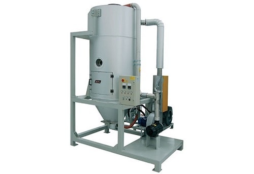
Image courtesy of Summit Systems Ltd
Hot air dryers are designed to remove surface moisture from non-hygroscopic (non-moisture absorbing) polymer, and also to preheat material before processing. They comprise an insulated stainless-steel hopper with an attached blower and heater. Hot air is blown through the polymer granules, and the wet air is then expelled to the atmosphere. These units are not suitable for use with materials that absorb moisture (hygroscopic).
Dehumidifying dryers are designed to remove any moisture present in the polymer before being processed (moisture held within the plastic granules due to absorption from the atmosphere). Air is forced through a desiccant bed to make it extremely dry. This air is then heated to a specified temperature and fed into a drying hopper containing the material to be dried. This hot, dry air draws the moisture out of the material. This removal of internal moisture is critical for hygroscopic material grades such as Nylon and ABS.
Compressed air dryers are designed to be fitted directly to the throat of smaller throughput machines. These compressed air dryers are compact and light in weight, but still use desiccant bed technology, making them ideally suited for the technical moulding sector. The units use factory compressed air rather than using the electric blowers that are typically fitted to larger floor standing dehumidifying units.
Vacuum dryers do not require the use of desiccants. After the material is heated with hot air, a vacuum is applied to it, which reduces pressure to a level below the vapour pressure of water, causing the water to boil off at a relatively low temperature. This reduces energy consumption and is less likely to cause material degradation.
Central material drying systems frequently form part of a larger material distribution system, removing moisture from the material before it is transported to the relevant equipment through distribution pipework and material handling equipment.
Drying usually takes part in a designated area within or adjacent to the production shop. Rather than using desiccant dryers with a single associated material hopper, banks of hoppers are often mounted on a common frame, with material diverted to them as required.
Visit here to contact the leading UK companies that can provide you with advice and quotes for your material drying requirements.

Image courtesy of Tool Temp Limited
In this context, temperature control refers to the water needed for the heating or cooling of tools and dies, as well as the cooling of heat-generating equipment such as hydraulic circuits.
In the case of tools and dies, the most frequent requirement is for chilled water. This is pumped around channels (water-ways) within the tool’s steel walls to speed up the solidification of the plastic within. In the case of injection moulding, it is also sometimes necessary to heat up one half of the tool using heated water or oil within the channels, to prevent the plastic from solidifying (chilling off) too quickly during the injection phase.
Temperature control units (TCUs), also known as thermoregulators or water heaters, are used to control the temperature of a fluid that circulates around the channels that require temperature regulation. A good example would be an injection mould tool that contains water-ways. Most TCUs use water, hence they are sometimes also called water heaters. If they use a pressurised water system, temperatures can be increased from the standard ceiling of around 90°C to around 140°C. For higher temperatures, TCUs that use oil as their circulated medium are capable of achieving around 350°C. In this case, specialised distribution hoses are also needed.
Industrial chillers are used to reduce the temperature of the water that is used for the cooling of moulds or the hydraulic circuits of processing machinery. In the case of moulds, chillers are used where it is necessary to remove excess heat, for example to achieve a fast cycle time when producing thin-walled products.
The chiller uses refrigerants and a pumping system to maintain a pre-set temperature within a water circuit. Smaller units can be used for individual moulds or machines, whereas larger units can be used for a ‘ring-main’ type system.
Free coolers are designed to reduce the temperature of water in a factory ring-main back to close to ambient levels. They are in effect giant radiators, similar to those used to cool a car engine’s oil. Machine hydraulic circuits don’t need chilled water, just water that is cooler than the oil in their heat exchangers.
Free coolers are typically sited outside a factory and in shade. This means that for a significant amount of time, it is only necessary to pump water around the circuit. In hot weather, electric fans engage to increase airflow across the radiator fins.
There are two basic types of free cooler:
Visit here to contact the leading UK companies that can provide you with advice and quotes for your chiller & temperature control requirements.
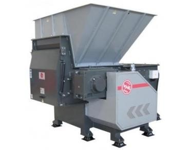
Image courtesy of Renmar Plastics Machinery Limited
Part reduction relates to the breaking down of scrap plastic components into smaller parts. This may be to reduce the volume of the items or to allow the material to be reprocessed.
Shredders are generally used to break down large items such as film bales, plastic purgings, automotive bumpers, pipes, profiles and even voluminous parts such as bins. Items are fed into a large hopper and drawn through the equipment by one or two rotating shafts. To reprocess the shredded material, it may first have to be granulated.
Granulators are used for reducing the size of plastic waste such as runner systems, smaller scrap components or pre-shredded material. This allows for the resulting plastic flake to be readily reprocessed.
Beside-the-press models are smaller units that can be located next to a processing machine, to be fed a runner system by a robot or sprue picker. The granulated material can then be fed back into the machine in a closed-loop system. Rotor type granulators operate at lower speeds and make less noise than ‘flying blade’ style units, so are better suited for this type of application.
Centralised processing systems are larger granulators that can be used to meet the needs of a whole factory, as they can process larger items in higher volumes. These centralised systems tend to be isolated from the rest of the production area, as noise levels can be high. A sizing grid (mesh) is used to make sure that the flake produced is below a specified size.
Units can usually be supplied with soundproofing enclosures and additional auxiliary items such as:
Edge trim granulators are specialised units designed to run continuously in conjunction with a plastic sheet extrusion line. Trim from one or both sheet edges is guided through adjustable rollers into the granulator.
Once processed, the resultant regrind is typically fed directly back into the production line (closed-loop).
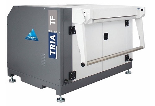
Image courtesy of Summit Systems Ltd in partnership with Tria S.p.A
Thermoforming granulators are used in conjunction with fully automated thermoforming lines, processing the skeletal waste produced by the process. During the startup process, the granulator is fed a full sheet of material.
The unit can be positioned either in-line with the processing machine, below the machine within the support frame, or in a pit, if the granulator is too large to fit within the frame. Rollers or other traction devices are used to guide and pull skeletal waste into the granulator.
Visit here to contact the leading UK companies that can provide you with advice and quotes for your granulator & shredder requirements.
Waste Balers are hydraulically powered units that crush materials within a chamber. The compaction of the material can significantly reduce its volume, making it easier to store and transport. In some cases, a volume reduction of up to 90% can be achieved.
Although Balers can help to reduce the volume of refuse destined for landfill, within the Plastics Sector, their primary function is to aid in the recycling of plastic scrap and cardboard. Both these commodities have value when sold to a specialist recycling company, so making them easier to store, handle and transport is good practice.
Balers vary significantly in their size and compacting power. The power of the hydraulic ‘press’ within a unit is measured in metric tonnes of force. In essence, the higher the force applied per unit of surface area (e.g., per cm²), the more compact and dense the resulting bale of material will be.
Lower tonnage models are ideal for cardboard and flexible plastic packaging materials such as film. If rigid plastics are to be processed, then a higher tonnage unit will need to be specified.
The most attractive format of bale for re-processors is the Mill Size Bale. This has the optimum size and density for transportation and handling. Some models of Waste Baler are called Mill Size Balers.
The advantages of converting plastic and cardboard waste into bales include:

Image courtesy of Compact and Bale Ltd.
- A 65tonne horizontal waste baler
capable of producing bales weighing
around 750kg.
Waste Balers have two basic designs: Vertical and Horizontal models. Vertical units are the most popular in a typical manufacturing or retail environment, as they take up less floor space. They are typically manually front-loaded. Horizontal models can be loaded by tipping material directly into the compacting chamber. They tend to provide higher material throughputs and a greater degree of compaction.
Depending on the intended throughput, Waste Balers can be offered with a degree of automation. Options include automated tieing and bale ejection, as well as feed systems such as inclined conveyors.