
Managing pressure loss in the moulding process is complicated and influenced by many factors outside your control. In this blog, RJG evaluates each of these areas to ensure you have a wide process window.
Have you ever encountered a part that has a process window thinner than a human hair? Not easy, is it?. But there’s a solution. Managing pressure loss in the moulding process can be complicated and influenced by many factors outside our control. By evaluating the following areas, you can significantly increase your process window.
Part Design
Ultimately, the success of moulding starts at the OEM. No matter the environment or application, a design engineer must understand how the geometry influences the success of each step along the way.
Part Thickness: The thickness of the part plays an important role in how difficult the moulding process will be. Typically, injection moulded parts will be between 0.040 and 0.250 inches thick. We can divide them into three separate categories within this large range: thin, intermediate, and thick.
Part Size: Another factor that can drastically influence the moulding success is how large the part is. To simplify this, we will use the overall length (OAL) of a part as an additional consideration. The OAL of injection moulded parts can also vary widely, just like thickness. Some parts could be as short as 0.250 inches in the medical industry. In the automotive or appliance industry, the OAL could be 60 inches.
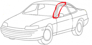
Example: Each part has its own challenges, but for the focus of this article, we will evaluate a thinner-walled part with a large OAL. The example below is an A-Pillar (Figure 1) for an automobile with a thickness of 0.080 inches and an OAL of 55 inches.
Material Selection
Viscosity: The first step of selecting a material is to evaluate the viscosity characteristics. Remember, viscosity is measuring the internal resistance to flow. Certain materials, like polycarbonates, will always be a high viscosity resin and will require higher injection pressure from the moulding machine to create flow.
Melt Flow Index: Next, the focus shifts to the Melt Flow Index (MFI) or Melt Flow Rate (MFR). The MFI or MFR will give a reference to the flowability of a material within a given type of resin. If we review the data in Table 1, we can see that there is a wide range of values for the flowability of each resin. When evaluating the MFI or MFR, it is imperative that a comparison is only done between the same types of resin (ABS to ABS, PC to PC, etc.).
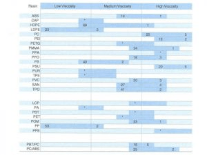
If the material that is selected at the start of the project is naturally a high viscosity resin and has a low MFI or MFR, the risk of moulding non-conformities increases drastically.
Variation: There will be variation and likely lots of it. The viscosity can deviate ±20%, depending on the quality of resin purchased. A typical virgin, wide spec resin will fall into this category. If there are additives, such as colour or glass, the amount of variation can be greater than ±20%. If regrind is added into the process, there can be a viscosity shift of ±40%.
Example: In a typical automotive application, the A-Pillar is moulded out of PC/ABS or PC/ASA. Given that PC/ABS is a medium to high viscosity resin, the material selection increases the risk of consistently moulding a quality product.
Mould Design
Now that we understand the size and material of the part to be moulded, it’s advisable to evaluate the mould design.
Aspect Ratio: First, we must review the aspect ratio, which is a comparison of the flow length to wall thickness (expressed XXX:1). Flow length starts at the gate and ends at the furthest point from the gate within the cavity. A high aspect ratio increases the probability of moulding non-conformities. When there are multiple gates required within the same part, it’s advised to balance the aspect ratio.
Gate Size: The size of the gate plays a crucial role in how well the material will flow. It also influences the ability to “pack out” the part. If the gates are too small, the injection pressure during fill will be very high, and the ability to pack out the part will be negatively impacted.

Example: In our example of the automotive A-Pillar, the material must flow 55 inches through a 0.080-inch thick wall, which yields an aspect ratio of 688:1. This ratio is extremely high if the part were to be single gated at one end. In this case, we would want multiple large gates strategically placed to reduce the aspect ratio. Also, since this part will likely be painted or chrome plated, knit lines are a concern. Given the cosmetic requirements, there is a good chance the mould would require sequential valve gates (SVG), shown in Figure 2.
Moulding Machine
The performance requirements of the moulding machine are essential to the success of any process. Here are three factors that need to be evaluated when selecting a machine:
- Volume: We must ensure that the injection unit has the correct volume to avoid un-melted pellets or degradation.
- Volumetric Flow Rate: We must understand the volumetric flow rate—this is critical. Thin wall parts require a higher volumetric flow rate to ensure the cavity is filled prior to the flow front freezing. Depending on the age of the moulding machine, volumetric flow rates can range from 5.0 in3/sec to 50 in3/sec.
- Plastic Pressure: We must consider the amount of plastic pressure a machine can produce in conjunction with the volumetric flow rate. As the volumetric flow rate requirements increase, so does the plastic pressure required to achieve and maintain a desired volumetric flow rate. Again, taking into consideration the vintage of equipment, the maximum injection pressure could be 20,000 PSIp to 45,000 PSIp.
Example: Given what we know about the part geometry, material viscosity, and use of SVGs in the mould for the A-Pillar, the flow rate would likely be around 8 in3/sec with peak plastic pressure during filling at near 25,000 PSIp.
Processing
Over the years, RJG has learned that achieving a pressure at the end of cavity (EOC) of 3,000 PSIp indicates the steps leading up to the process have allowed for a wide process window.
This is not to say that parts cannot be moulded with less than 3,000 PSIp at the EOC; they can. However, the lower pressure that can be obtained at the EOC and the amount of risk associated with moulding non-conformities increases exponentially.
In a DECOUPLED MOLDING® II process, if the viscosity of the material increases, the pressure at the EOC decreases unless process changes are made. When pressure loss is greater than the validation, some moulding non-conformities that can be expected are undersized dimensions, warp, sinks, and short shots.
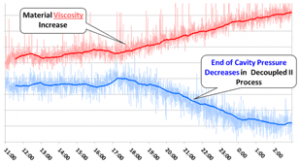
In Chart 1, the trend data from a 15-hour production run is displayed. The mould is equipped with cavity pressure sensors at the EOC, the machine is equipped with a hydraulic pressure sensor to monitor shifts in viscosity, and the data is displayed on an eDART® or CoPilot® summary graph. Here the inverse correlation between viscosity and EOC peak pressure can be easily seen.
Example: In the A-Pillar application, we stated that the EOC has a peak of 3,000 PSIp at PPAP. If the viscosity increases by 20%, which is likely to occur over the life of the program, it could result in an EOC peak of 1,800 PSIp. If no process adjustments are made, we could expect parts that are undersized, warped or have sinks over thick sections.
If a DECOUPLED MOLDING III process strategy is selected, it can reduce the variation that is seen in the cavity when the material viscosity inevitably changes.
Conclusion
When trying to manage pressure loss, we must first consider the thickness and size of the part. Second, evaluate the MFI of the material against the geometry in which it must flow. Not only do we have to consider the MFI at the onset of the project, but the variation of material over time. Next, consider the mould design to ensure the aspect ratio is correct. Also, determine what the performance criteria is of the moulding machine responsible for production. Finally, determine if the correct processing strategy was selected. If one of these critical areas is overlooked, it won’t be easy to produce quality parts regularly.
In short, if the part has a thin wall and long OAL and is running a high viscosity, low MFI resin, and a high aspect ratio, the likelihood of achieving 3,000 PSIp at the EOC is extremely low. A thorough evaluation of all the steps is required as well as a better process control method.
For more informative injection moulding articles like this one, visit the RJG Blog Archive.
Have any questions or want to talk to one of the expert consultants at RJG? Use the details listed below to get in touch with the team.
![]()